


As a transmission mechanism, planetary gear is widely used in various engineering practices, such as gear reducer, crane, planetary gear reducer, etc. For planetary gear reducer, it can replace the transmission mechanism of fixed axle gear train in many cases. Because the process of gear transmission is line contact, long time meshing will cause gear failure, so it is necessary to simulate its strength. Li Hongli et al. used the automatic meshing method to mesh the planetary gear, and obtained that the torque and the maximum stress are linear. Wang Yanjun et al. also meshed the planetary gear through the automatic generation method, and simulated the statics and modal simulation of the planetary gear. In this paper, tetrahedron and hexahedron elements are mainly used to divide the mesh, and the final results are analyzed to see whether the strength conditions are met.
1、 Model establishment and result analysis
Three dimensional modeling of planetary gear
Planetary gear is mainly composed of ring gear, sun gear and planetary gear. The main parameters selected in this paper are: the number of teeth of the inner gear ring is 66, the number of teeth of the sun gear is 36, the number of teeth of the planetary gear is 15, the outer diameter of the inner gear ring is 150 mm, the modulus is 2 mm, the pressure angle is 20 °, the tooth width is 20 mm, the addendum height coefficient is 1, the backlash coefficient is 0.25, and there are three planetary gears.
Static simulation analysis of planetary gear
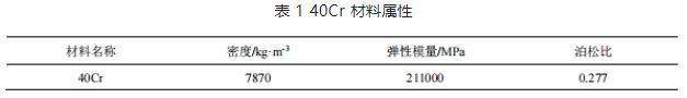
Define material properties: import the three-dimensional planetary gear system drawn in UG software into ANSYS, and set the material parameters, as shown in Table 1 below:
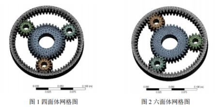
Meshing: The finite element mesh is divided by tetrahedron and hexahedron, and the basic size of the element is 5mm. Since the planetary gear, sun gear and inner gear ring are in contact and mesh, the mesh of the contact and mesh parts is densified, and the size is 2mm. First, tetrahedral grids are used, as shown in Figure 1. 105906 elements and 177893 nodes are generated in total. Then hexahedral grid is adopted, as shown in Figure 2, and 26957 cells and 140560 nodes are generated in total.
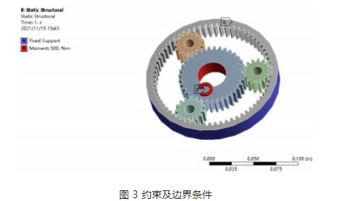
Load application and boundary conditions: according to the working characteristics of the planetary gear in the reducer, the sun gear is the driving gear, the planetary gear is the driven gear, and the final output is through the planetary carrier. Fix the inner gear ring in ANSYS, and apply a torque of 500N · m to the sun gear, as shown in Figure 3.
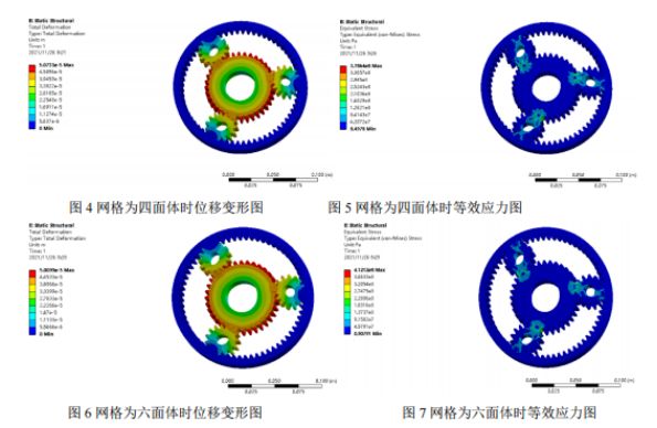
Post processing and result analysis: The displacement nephogram and equivalent stress nephogram of static analysis obtained from two grid divisions are given below, and comparative analysis is conducted. From the displacement nephogram of the two kinds of grids, it is found that the maximum displacement occurs at the position where the sun gear does not mesh with the planetary gear, and the maximum stress occurs at the root of the gear mesh. The maximum stress of the tetrahedral grid is 378MPa, and the maximum stress of the hexahedral grid is 412MPa. Since the yield limit of the material is 785MPa and the safety factor is 1.5, the allowable stress is 523MPa. The maximum stress of both results is less than the allowable stress, and both meet the strength conditions.
2、 Conclusion
Through the finite element simulation of the planetary gear, the displacement deformation nephogram and equivalent stress nephogram of the gear system are obtained, from which the maximum and minimum data and their distribution in the planetary gear model can be found. The location of the maximum equivalent stress is also the location where the gear teeth are most likely to fail, so special attention should be paid to it during design or manufacturing. Through the analysis of the whole system of planetary gear, the error caused by the analysis of only one gear tooth is overcome.
Post time: Dec-28-2022