


Bevel gears play a vital role in power transmission, and understanding their orientation is critical to the efficient operation of machinery. The two main types of bevel gears are straight bevel gears and spiral bevel gears.
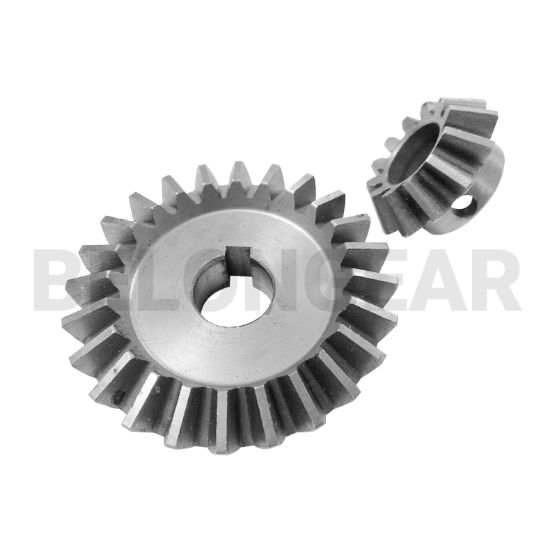
Straight bevel gear:
Straight bevel gears have straight teeth that taper toward the apex of the cone. Here’s how to determine its direction:
Stand image:
Imagine standing at the intersection of two axes.
Clockwise movement of one gear causes counterclockwise movement of the other gear and vice versa.
The direction of rotation is usually described with respect to the input (drive gear) and output (driven gear).
What are bevel gears and what are its types?
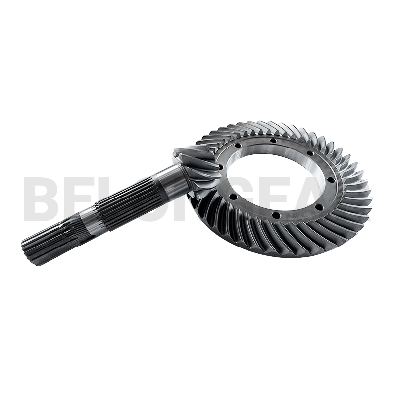
Spiral bevel gear:
Spiral bevel gears differ in that they have spiral-shaped arc teeth surrounding the gear. Determine their orientation as follows:
Curvature observation:
Check the side of the gear’s helix away from the shaft.
Clockwise curvature means clockwise rotation and vice versa.
Gear symbol:
The gear symbol provides a concise representation of the direction of power transmission:
Standard symbols:
Gears are often represented as “A to B” or “B to A.”
“A to B” means that gear A rotating in one direction causes gear B to rotate in the opposite direction.
Meshing Dynamics:
Observing the mesh of the gear teeth can help determine the direction of rotation,
Engagement point tracking:
When gears mesh, the teeth contact each other.
Follow the points of contact as one gear turns to identify the direction of rotation of the other gear.
Post time: Dec-25-2023