


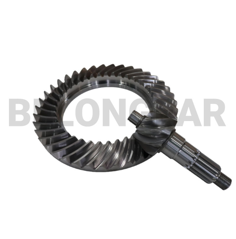
Gleason spiral bevel gears are a specialized type of bevel gear designed to transmit power between intersecting shafts, usually at a 90 degree angle. What makes the Gleason system distinct is its unique tooth geometry and manufacturing method, which provide smooth motion, high torque capacity, and quiet operation. These gears are widely used in automotive, industrial, and aerospace transmissions where reliability and precision are critical.
The Gleason system was developed to improve upon straight and zerol bevel gears by introducing a curved, spiral shaped tooth. This spiral form enables gradual engagement between the teeth, significantly reducing noise and vibration while allowing higher rotational speeds and load capacity. The design also enhances contact ratio and surface strength, ensuring efficient power transmission under heavy or dynamic loads.
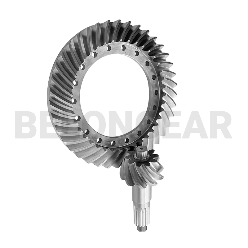
Each Gleason spiral bevel gear pair consists of a pinion and a mating gear, produced with matched geometry. The manufacturing process is highly specialized. It begins with forging or precision casting of alloy steel blanks, such as 18CrNiMo7-6, followed by rough cutting, hobbing, or shaping to generate the initial gear form. Advanced methods like 5-axis machining, skiving, and hard cutting ensure high dimensional accuracy and optimized surface finish. After heat treatment such as carburization (58–60 HRC), the gears undergo lapping or grinding to achieve perfect meshing between the pinion and gear.
The geometry of Gleason spiral bevel gears is defined by several critical parameters—spiral angle, pressure angle, pitch cone distance, and face width. These parameters are precisely calculated to ensure correct tooth contact patterns and load distribution. During the final inspection, tools such as the coordinate measuring machine (CMM) and tooth contact analysis (TCA) verify that the gear set meets the required DIN 6 or ISO 1328-1 precision class.
In operation, Gleason spiral bevel gears offer high efficiency and stable performance even under demanding conditions. The curved teeth provide continuous contact, reducing stress concentration and wear. This makes them ideal for automotive differentials, truck gearboxes, heavy machinery, marine propulsion systems, and power tools. In addition, the ability to customize tooth geometry and mounting distance allows engineers to optimize the design for specific torque, speed, and space constraints.
Gleason-type spiral bevel gear — key calculation table
| Item | Formula / Expression | Variables / Notes |
|---|---|---|
| Input parameters | (z_1,\ z_2,\ m_n,\ \alpha_n,\ \Sigma,\ b,\ T) | pinion/gear teeth (z); normal module (m_n); normal pressure angle (\alpha_n); shaft angle (\Sigma); face width (b); transmitted torque (T). |
| Reference (mean) diameter | (d_i = z_i , m_n) | i = 1 (pinion), 2 (gear). Mean/reference diameter in the normal section. |
| Pitch (cone) angles | (\delta_1,\ \delta_2) such that (\delta_1+\delta_2=\Sigma) and (\dfrac{\sin\delta_1}{d_1}=\dfrac{\sin\delta_2}{d_2}) | Solve for cone angles consistent with tooth proportions and shaft angle. |
| Cone distance (pitch apex distance) | (R = \dfrac{d_1}{2\sin\delta_1} = \dfrac{d_2}{2\sin\delta_2}) | Distance from cone apex to pitch circle measured along generatrix. |
| Circular pitch (normal) | (p_n = \pi m_n) | Linear pitch at the normal section. |
| Transverse module (approx) | (m_t = \dfrac{m_n}{\cos\beta_n}) | (\beta_n) = normal spiral angle; transforms between normal and transverse sections as needed. |
| Spiral angle (mean/transverse relation) | (\tan\beta_t = \tan\beta_n \cos\delta_m) | (\delta_m) = mean cone angle; use transforms between normal, transverse, and mean spiral angles. |
| Face width recommendation | (b = k_b , m_n) | (k_b) typically chosen from 8 to 20 depending on size and application; consult design practice for exact value. |
| Addendum (mean) | (a \approx m_n) | Standard full-depth addendum approximation; use exact tooth proportion tables for precise values. |
| Outside (tip) diameter | (d_{o,i} = d_i + 2a) | i = 1,2 |
| Root diameter | (d_{f,i} = d_i – 2h_f) | (h_f) = dedendum (from gear system proportions). |
| Circular tooth thickness (approx) | (s \approx \dfrac{\pi m_n}{2}) | For bevel geometry use corrected thickness from tooth tables for accuracy. |
| Tangential force at pitch circle | (F_t = \dfrac{2T}{d_p}) | (T) = torque; (d_p) = pitch diameter (use consistent units). |
| Bending stress (simplified) | (\sigma_b = \dfrac{F_t \cdot K_O \cdot K_V}{b \cdot m_n \cdot Y}) | (K_O) = overload factor, (K_V) = dynamic factor, (Y) = form factor (bending geometry). Use full AGMA/ISO bending equation for design. |
| Contact stress (Hertz-type, simplified) | (\sigma_H = C_H \sqrt{\dfrac{F_t}{d_p , b} \cdot \dfrac{1}{\frac{1-\nu_1^2}{E_1}+\frac{1-\nu_2^2}{E_2}}}) | (C_H) geometry constant, (E_i,\nu_i) material elastic moduli and Poisson ratios. Use full contact-stress equations for verification. |
| Contact ratio (general) | (\varepsilon = \dfrac{\text{arc of action}}{\text{base pitch}}) | For bevel gears compute using pitch cone geometry and spiral angle; typically evaluated with gear design tables or software. |
| Virtual number of teeth | (z_v \approx \dfrac{d}{m_t}) | Useful for contact/undercut checks; (m_t) = transverse module. |
| Minimum teeth / undercut check | Use minimum teeth condition based on spiral angle, pressure angle and tooth proportions | If (z) is below the minimum, undercut or special tooling required. |
| Machine/cutter settings (design step) | Determine cutter head angles, cradle rotation and indexing from gear system geometry | These settings are derived from the gear geometry and cutter system; follow machine/tooling procedure. |
Modern production technology, such as CNC bevel gear cutting and grinding machines, ensures consistent quality and interchangeability. By integrating computer-aided design (CAD) and simulation, manufacturers can perform reverse engineering and virtual testing before actual production. This minimizes lead time and cost while improving precision and reliability.
In summary, Gleason spiral bevel gears represent the perfect combination of advanced geometry, material strength, and manufacturing precision. Their ability to deliver smooth, efficient, and durable power transmission has made them an indispensable component in modern drive systems. Whether used in automotive, industrial, or aerospace sectors, these gears continue to define excellence in motion and mechanical performance.
Post time: Oct-24-2025